

Measurement is one of the most essential aspects of science, engineering, and manufacturing. Accurate measurements ensure quality, functionality, and safety of parts and assemblies. Among the various precision instruments used in metrology, the micrometer holds a special place due to its exceptional accuracy and reliability. This instrument, though simple in appearance, allows technicians, engineers, and machinists to measure dimensions down to a few microns. Understanding the micrometer’s structure, principle, and operation helps in achieving precision in every mechanical or industrial process.
1. Introduction to Micrometer
A micrometer, also known as a micrometer screw gauge, is a precision measuring instrument used to measure small linear dimensions with extremely high accuracy. It operates on the principle of a finely threaded screw mechanism, converting small linear movements into readable measurements. Typically, a micrometer can measure dimensions up to the nearest 0.01 mm or 0.001 inch, depending on its type.
The micrometer is commonly used in mechanical workshops, laboratories, and industries that require fine dimensional accuracy, such as aerospace, automotive, machining, and manufacturing sectors. It is mainly used to measure thickness, outer diameters, inner diameters, and depths of objects that are too small for a regular ruler or vernier caliper to measure precisely.
2. History and Development of the Micrometer
The concept of the micrometer can be traced back to the 17th century when William Gascoigne, an English astronomer, used a screw-based device to measure the distance between celestial bodies. Later, in the 19th century, Jean Laurent Palmer refined the design and created a compact, handheld version for mechanical use, which became the foundation for the modern micrometer screw gauge. This development marked a revolution in precision measurement, allowing machinists to measure dimensions more accurately than ever before.
3. Principle of Working
The working principle of a micrometer is based on the screw and nut mechanism. It converts the small rotational movement of a screw into precise linear movement of a spindle. The pitch of the screw determines how far the spindle moves for each complete rotation of the thimble.
Example of Measurement Conversion:
If the screw has a pitch of 0.5 mm, it means that one full rotation of the thimble moves the spindle forward or backward by 0.5 mm. The thimble is divided into 50 equal divisions. Therefore, each division on the thimble represents a movement of: Least Count=PitchNumber of divisions on thimble=0.550=0.01 mm\text{Least Count} = \frac{\text{Pitch}}{\text{Number of divisions on thimble}} = \frac{0.5}{50} = 0.01\ \text{mm}Least Count=Number of divisions on thimblePitch=500.5=0.01 mm
Thus, the micrometer can measure up to 0.01 mm (10 microns) precisely.
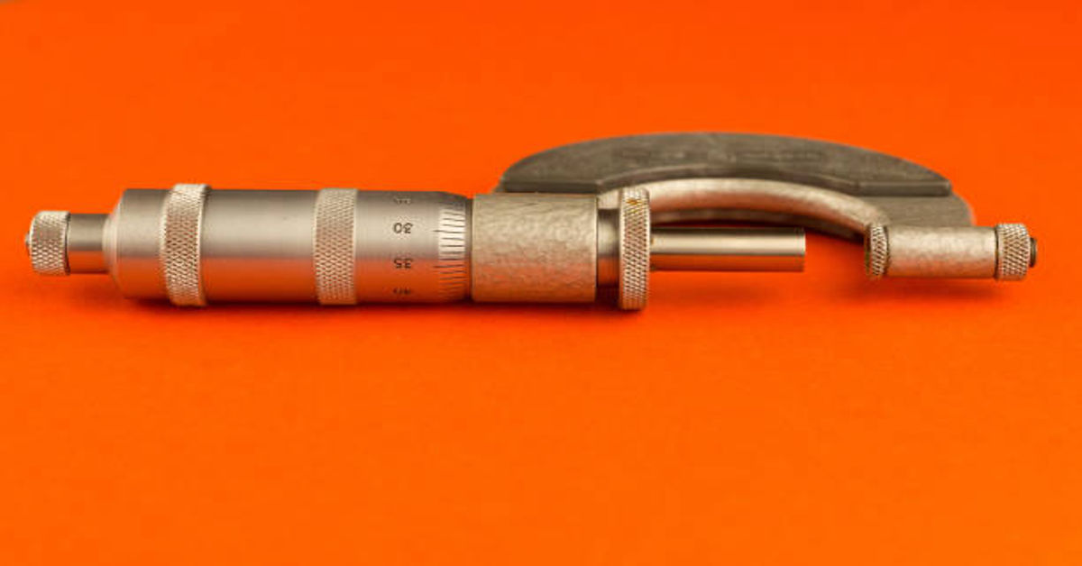
4. Main Parts of a Micrometer
A micrometer consists of several precisely engineered components, each playing an essential role in its accuracy and usability.
| Part Name | Function / Description |
|---|---|
| Frame | The rigid U-shaped structure that supports the anvil and barrel, ensuring stability during measurement. |
| Anvil | The fixed measuring surface against which the object to be measured is held. |
| Spindle | The movable measuring surface that advances or retracts as the thimble is rotated. |
| Sleeve (Barrel) | A stationary cylindrical part engraved with the main scale (in mm or inches). |
| Thimble | The rotating part attached to the spindle, carrying the secondary scale (thimble scale). |
| Ratchet Stop | A small knob that ensures uniform pressure is applied during measurement, preventing errors. |
| Lock Nut (Lock Ring) | Used to fix the spindle in position after the measurement has been taken. |
| Carbide Faces | Hard surfaces on anvil and spindle to resist wear and maintain accuracy. |
Each component must be machined with great precision to ensure smooth movement and zero backlash, which could otherwise affect measurement accuracy.
5. Types of Micrometers
There are several types of micrometers, each designed for a specific purpose or type of measurement. Below is a detailed classification:
| Type of Micrometer | Measurement Type | Description / Application |
|---|---|---|
| Outside Micrometer | External dimensions | Measures outside diameters or thickness of objects such as wires, rods, and sheets. |
| Inside Micrometer | Internal dimensions | Measures internal diameters of holes, cylinders, or pipes. |
| Depth Micrometer | Depth measurement | Measures the depth of holes, slots, and recesses. |
| Digital Micrometer | Electronic display | Provides direct digital readings with higher accuracy and ease of use. |
| Bench Micrometer | Precision laboratory use | Fixed on a stand for higher stability and accuracy, used in laboratories and inspection rooms. |
| Blade Micrometer | Small grooves | Measures narrow slots or grooves where standard anvils cannot reach. |
| Screw Thread Micrometer | Thread pitch diameter | Measures pitch diameters of threads using V-anvil and conical spindle. |
| Tubular Micrometer | Tube wall thickness | Designed to measure the thickness of tubes and pipes. |
| Gear Tooth Micrometer | Gear tooth thickness | Used to measure the thickness of gear teeth at the pitch line. |
6. Least Count of a Micrometer
The least count is the smallest value that can be accurately measured by an instrument. For most standard micrometers, the least count is 0.01 mm. It is determined by dividing the pitch of the screw by the number of divisions on the thimble scale.
For example:
| Parameter | Value |
|---|---|
| Pitch of screw | 0.5 mm |
| Divisions on thimble | 50 |
| Least Count | 0.01 mm |
Digital micrometers may have even smaller least counts such as 0.001 mm (1 micron) due to electronic sensors and displays.
7. Procedure for Measuring with a Micrometer
Using a micrometer properly is essential for obtaining accurate readings. The following steps outline the standard measurement procedure:
- Clean the Micrometer and Workpiece
Ensure that both the micrometer faces and the surface of the object are clean and free from dust, oil, or burrs. - Check for Zero Error
Close the spindle until it touches the anvil lightly using the ratchet stop. The reading should be exactly zero. If not, note the zero error. - Place the Object
Insert the object between the anvil and spindle gently. - Rotate the Thimble
Turn the thimble until the spindle just contacts the object. Use the ratchet stop to apply uniform pressure. - Lock the Spindle
Use the lock nut to hold the spindle in position, preventing accidental movement. - Read the Measurement
Observe the main scale reading on the sleeve, then add the thimble scale reading. Apply any zero correction if needed. - Record the Result
Write the final value in millimeters or inches depending on the micrometer’s calibration.
8. Reading a Micrometer (Metric Example)
A metric micrometer typically has a main scale on the sleeve and a rotating thimble scale. To read it:
- Main Scale Reading
The main scale is graduated in millimeters and half-millimeters. If the last visible line on the sleeve before the thimble edge is 5.5 mm, that’s the main scale reading. - Thimble Scale Reading
The thimble has 50 divisions, each representing 0.01 mm. If the thimble shows 28 divisions, multiply by 0.01 mm = 0.28 mm. - Final Reading Total=5.5+0.28=5.78 mm\text{Total} = 5.5 + 0.28 = 5.78\ \text{mm}Total=5.5+0.28=5.78 mm
So, the diameter of the object is 5.78 mm.
9. Zero Error and Its Correction
Zero error occurs when the zero mark of the thimble does not coincide with the reference line on the sleeve when the anvil and spindle are in contact.
| Type of Error | Condition | Correction |
|---|---|---|
| Positive Zero Error | Zero line of thimble is below reference line | Subtract error from measured reading |
| Negative Zero Error | Zero line of thimble is above reference line | Add error to measured reading |
For accurate results, always check for zero error before taking measurements and apply correction accordingly.
10. Advantages of Micrometer
- High Accuracy: Provides precise measurements up to 0.01 mm or better.
- Ease of Use: Simple construction and easy to read once familiar with scales.
- Durability: Made of robust materials, often with carbide-tipped faces for longevity.
- Consistency: Ratchet mechanism ensures uniform measuring pressure.
- Versatility: Different types available for diverse measurement needs.
- Compact and Portable: Handy instrument suitable for workshops and field use.
11. Limitations of Micrometer
Despite its precision, the micrometer has a few limitations:
- Limited Range: Most micrometers measure only a small range (e.g., 0–25 mm).
- Skill Required: Reading errors may occur if the user lacks experience.
- Temperature Sensitivity: Expansion of metal can affect accuracy in varying temperatures.
- One-Dimensional Measurement: Each micrometer is designed for a specific dimension only (outside, inside, or depth).
- Maintenance Need: Regular calibration and cleaning are required to maintain accuracy.
12. Applications of Micrometer
Micrometers are indispensable in numerous industries due to their reliability in precision measurement.
| Industry / Field | Application |
|---|---|
| Manufacturing | Measuring diameters of machined components and shafts. |
| Automobile Industry | Checking wear in engine parts like crankshafts or pistons. |
| Aerospace | Ensuring precise fit and alignment of aircraft components. |
| Tool and Die Making | Inspecting tools, dies, and molds for dimensional accuracy. |
| Metalworking | Measuring thickness of sheets, rods, and wires. |
| Laboratories | Used for calibration and material testing. |
| Educational Institutes | Training students in precision measurement. |
13. Maintenance and Care of a Micrometer
Proper maintenance ensures the longevity and accuracy of a micrometer.
- Clean Regularly: Wipe the measuring faces after use with a soft, lint-free cloth.
- Avoid Over-tightening: Always use the ratchet stop to prevent excessive pressure.
- Store Properly: Keep in a protective case to avoid dust and mechanical shocks.
- Avoid Extreme Temperatures: Thermal expansion can cause measurement deviations.
- Calibration: Regular calibration using gauge blocks ensures continued accuracy.
- Lubrication: Apply a thin layer of oil on threads occasionally to prevent rust.
14. Calibration of a Micrometer
Calibration ensures the micrometer maintains its measurement accuracy over time. It is performed using standard gauge blocks of known dimensions.
Calibration Steps:
- Clean both the micrometer and gauge blocks.
- Set the micrometer to zero and check for any zero error.
- Measure the gauge block and compare with its actual size.
- Note the difference (if any) and adjust the micrometer accordingly.
- Record calibration data for reference.
Calibration should be performed periodically, especially in industrial environments where the instrument is frequently used.
15. Comparison: Micrometer vs. Vernier Caliper
| Parameter | Micrometer | Vernier Caliper |
|---|---|---|
| Least Count | 0.01 mm or 0.001 mm | 0.02 mm |
| Accuracy | Higher | Moderate |
| Ease of Use | Simple for single dimension | Measures internal, external, and depth |
| Range | Limited (25 mm per unit) | Larger (up to 300 mm or more) |
| Portability | Compact | Slightly larger |
| Price | Generally higher | Moderate |
While both are precision instruments, the micrometer provides higher accuracy but over a smaller measuring range compared to a vernier caliper.
16. Modern Digital Micrometers
With advancements in technology, digital micrometers have gained popularity. They feature electronic sensors and LCD displays that directly show readings, eliminating manual calculation errors.
Features of Digital Micrometer:
- Instant digital display of measurements.
- Can switch between metric and inch units.
- Data output for computer connectivity.
- Auto power-off function for energy saving.
- Memory hold and preset features.
Digital micrometers are now widely used in automated inspection systems and quality control laboratories.
17. Micrometer Screw Thread Details
A micrometer’s precision relies heavily on the accuracy of its internal screw thread. The screw is manufactured with extremely fine threads and undergoes lapping or polishing to minimize backlash. The pitch, which defines the distance the spindle moves per revolution, is the foundation of the instrument’s accuracy. For standard metric micrometers, the pitch is usually 0.5 mm.
The screw and nut assembly are made of hardened steel or carbide-coated materials to reduce wear and maintain accuracy over long-term usage.
18. Sources of Error in Micrometer Measurement
Accuracy may be affected by several sources of error:
- Parallax Error: Occurs when the eye is not aligned correctly with the scale markings.
- Temperature Effects: Expansion or contraction of components changes measurement.
- Dirt or Burrs: Dust, oil, or burrs on surfaces can introduce inaccuracies.
- Improper Pressure: Too much or too little measuring force causes deformation of the object.
- Wear and Tear: Frequent use may wear down screw threads, affecting calibration.
- Zero Error: Misalignment between zero marks at closed position.
Proper handling, regular calibration, and environmental control help minimize these errors.
19. Advantages of Digital Micrometers over Analog Types
| Feature | Analog Micrometer | Digital Micrometer |
|---|---|---|
| Reading Method | Manual scale reading | Direct digital display |
| Accuracy | ±0.01 mm | ±0.001 mm |
| Ease of Use | Requires skill | Easy, quick reading |
| Data Storage | None | Memory and data transfer options |
| Human Error | Possible | Negligible |
| Cost | Lower | Higher |
20. Micrometer in Quality Control
In modern industries, micrometers play a crucial role in maintaining product quality. Every batch of manufactured components must pass dimensional checks before assembly or dispatch. Micrometers ensure that each part adheres to the specified tolerance limits. In quality control laboratories, micrometers are often paired with Go/No-Go gauges, dial indicators, and coordinate measuring machines (CMMs) for comprehensive dimensional analysis.
Accurate measurement ensures product interchangeability, safety, and customer satisfaction — all of which are vital for maintaining a company’s reputation and reducing production waste.
21. Safety Precautions While Using a Micrometer
- Never drop or knock the instrument against hard surfaces.
- Do not overtighten the spindle; use the ratchet only.
- Always close the micrometer lightly when not in use.
- Avoid measuring hot or rough surfaces.
- Handle the instrument gently and with clean hands.
- Use a protective case for storage.
Following these precautions ensures both user safety and instrument longevity.
22. Future Trends in Micrometer Technology
The field of precision measurement continues to evolve. Some trends shaping the future of micrometer technology include:
- Wireless Data Transfer: Integration with IoT for automatic data logging.
- Smart Calibration Systems: Self-calibrating micrometers with embedded sensors.
- Nano-Resolution Micrometers: Capable of measuring in nanometer scales for semiconductor industries.
- 3D Measurement Integration: Combining micrometer readings with digital 3D modeling systems.
- AI-Assisted Inspection: Automated analysis of data for predictive maintenance and quality assurance.
Conclusion
The micrometer remains one of the most indispensable tools in precision measurement. From its humble beginnings as a screw-based device to the advanced digital versions used today, the micrometer has evolved but its fundamental purpose — accuracy — has remained unchanged. Mastery of this instrument is crucial for anyone involved in manufacturing, engineering, or scientific research. Understanding its working principle, proper usage, calibration, and maintenance ensures long-lasting performance and dependable accuracy. In an era where every micron counts, the micrometer truly stands as a symbol of precision engineering.
Frequently Asked Questions (FAQs)
1. What is the least count of a standard micrometer?
The least count of a standard metric micrometer is 0.01 mm, determined by dividing the screw pitch (0.5 mm) by the number of thimble divisions (50).
2. How is a micrometer different from a vernier caliper?
A micrometer provides higher accuracy and measures smaller dimensions but has a limited range. Vernier calipers are more versatile but less precise.
3. What is the purpose of the ratchet stop on a micrometer?
The ratchet stop ensures uniform measuring pressure is applied, preventing user-induced errors and protecting both instrument and workpiece.
4. How often should a micrometer be calibrated?
In industrial environments, micrometers should be calibrated every 3–6 months or after heavy usage to maintain measurement reliability.
5. Can micrometers measure internal dimensions?
Yes, but only inside micrometers are designed for that purpose. Standard outside micrometers measure external dimensions such as diameter and thickness.
